Welcome to AU FOCUS Pty Ltd
Our Mission:
To become your most comprehensive and reliable Supplier, Installer & Maintenance Servicing Company providing a huge range of Diesel Heaters to Australia to suit our customer’s every need in both quality and budget:
AU FOCUS Pty Ltd is 100% Australian owned and a business providing: –
Supplying the right Diesel Heater for your requirements
Installation or assisting with your DIY project
Maintenance & servicing:- To bring a safe, reliable, simple to install and operate source of comfort and warmth to our customers enabling them to enjoy their activities whatever and wherever it may be.
Our Diesel Heaters are our signature product, and we can provide you with a warm and comfortable solution during cold weather that is a safe, simple, and effective heating system for caravans, RVs, boats, garages, and motor homes.
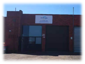
Company Location
Unit 11, 21-23 Capella Cres,
Moorabbin VIC 3198, AU
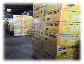
Warehouse
We have over one thousand products in stock
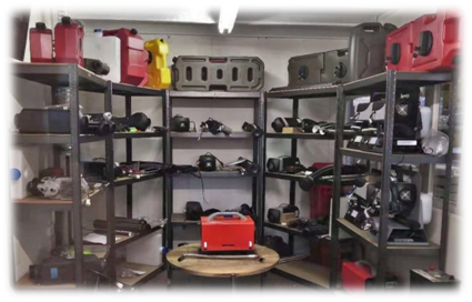
Display Room
AU FOCUS Pty Ltd
Provides this comprehensive document with every diesel heater purchased to assist our customers in understanding all the facts about how their newly purchased diesel heaters:
- Operates and its key functionality principles.
- Detailed installation instructions.
- Important points to watch out for during installation.
Diesel Heater Operational Overview:
This device uses direct current (DC) to electrically operate the computer and the unit generally & diesel fuel as the heating source. Diesel and fresh air are introduced into the aluminium burn chamber from underneath the unit to produce ignition under the control of a sophisticated computer.
The heat generated in the burn chamber heats the aluminium blades on the outside of the burn chamber. Ambient air within the area to be heated is drawn in by a fan through the intake duct. This air is then heated as it flows over & through the aluminium blades on the outside of the burn chamber to complete the heat exchange process and is expelled into the space requiring heating. This process continues until the room temperature reaches the set (or target) temperature.
The entire start-up, reaching & maintaining the target temperature, shutdown, and fault analysis is managed by the powerful onboard computer and can be viewed on the control panel at any time during the process.
(Note: The diesel heater fuel is DIESEL ONLY)
Machine Installation and location
The heater must be installed on a flat surface. It can also be installed horizontally on wall. (Make sure the glow plug is at the top).
The Heater is not designed for being mounted outdoors. It is not weatherproof. If the heater must be mounted outdoors, it must be fully covered and completely waterproof.
DIESEL HEATER & DIY INSTALLATION:
These heaters & the components shown below are required for Do It Yourself (DIY) installation including the fuel tank, fuel line & fuel pump connection and installation.
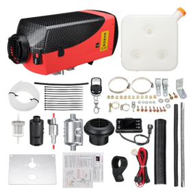
ALL IN ONE DIESEL HEATER
This product Fuel line and tank have been installed over
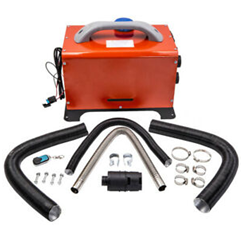
ADDITITIONAL ITEMS PROVIDED: (Maintenance Tools)
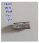
1. Tool 1 is used to pick the fuel atomizing net out from the glow plug.
2. Tool 2 is used to unscrew the glow plug.
3. Tool 3 is used as a lever in conjunction with tool 2 and can press the new fuel atomizing net back into place.
Replace parts:
General Introduction:
Most of the essential components of our diesel heaters are made in Japan and China. Therefore, our customers are rewarded with a far more economic price compared to German and Russian products.
Key features:
- Power cable loom is made in Japan
- Control panel computer motherboard is made in Taiwan
- Premium fuel pump is made using copper instead of steel.
There are two models based on the output power: 2kw and 5kw. In fact, the output power can be adjusted by temperature settings. (Please Note: There are 8kW models on the market. They have the same components as 5kW models. The only difference being the parameter settings within their electronic system.)
There are three different voltage choices:
- DC 12V
- DC24V
- AC240V which includes an adaptor to switch powder from AC240 to DC 12V or DC 24V
COMPUTERISED OPERATIONAL SAFETY CONTROL:
Overload protection:
- B & C series :15A fuse to protect the electrical cable;T series 30A.
- Overvoltage and undervoltage protection circuit
- Overcurrent and short current protection circuit
Overheating protection:
- A temperature sensor is mounted on the aluminium blades to monitor the heaters operating temperature.
- The heater will automatically shut down when temperature exceeds the parameters set in the computer.
Other protection
Two temperature sensors integrated with the fan and Mother Board, monitor the temperature difference. The heater will shut down when the temperature difference is outside the parameters set in the computer.
Quick Start Guide:
PLEASE NOTE: PAIRING THE REMOTE-CONTROL UNIT WITH THE HEATER HAS ALREADY BEEN COMPLETED
CONTROL PANEL DETAILS

1.MANUAL FUEL PUMP PRIMING OPERATION
Adopt this procedure following initial Installation of the heater or after draining the system & before any attempt to Start the Heater
It is important to prime the dosing pump prior to the initial start-up after installation or after draining the system. The dosing pump will run independently to pump the fuel through the fuel line and into the combustion chamber. Undertake the steps shown as follows:
- 1.1 From Default Screen, hold “OK” and “▼” button simultaneously, until the display shows “H oF”.
- 1.2 Press “▲” button, the fuel pump will start and commence the priming process with the display showing “H oN”.
- 1.3 When there is no excess air in fuel line. press “▼” button to stop the priming process.
2. REMOTE CONTROL UNIT PAIRING PROCESS.
Adopt this procedure following initial Installation of the heater or after draining the system & before any attempt to Start the Heater
It is important to prime the dosing pump prior to the initial start-up after installation or after draining the system. The dosing pump will run independently to pump the fuel through the fuel line and into the combustion chamber. Undertake the steps shown as follows:
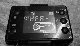
- 2.1 In the Off-state hold “▲” Button and “OK” Button simultaneously until the display shows “HFA-“. (For some LCD panel: In the Off-state hold “▲” Button until the display shows “HFA-“.)
- 2.2 When the Controller shows “HFA- “press the “OFF” button on the remote control unit.
- 2.3 Then using the remote, press “ON” and the heater will start.
3. TEMPERATURE CONTROL MODE SWITCHING (between Hz and °C)
- 3.1 From Default Screen, Press “▲” and SETTING button to display “P-x.x“(x.x represents the volume of fuel being pumped per dose from the dosing pump.)
- 3.2 From Default Screen, Press “▲” and SETTING button again will reverse the setting from Hz to Centigrade
4. DIESEL HEATER OPERATING PARAMETERS
From the Default Screen, press “OK” and it will show you four parameters.
- 4.1 Press once and the current temperature (or Hz, Number show as item 5) will display.
- 4.2 Press twice and the target temperature (or Hz, Number show as item 5) will display.
- 4.3 Press three times and the current voltage will display. (Note: the heater will not start if current voltage is out of safety range)
5. DEFAULT OPERATING PARAMETERS (advanced setting)
(Warning: AU FOCUS Pty Ltd will not take responsibility for any consequences if parameters are changed from default)
Refer to this list of parameters as a reference should you modify the default parameters
Your Content Goes Here
DC 12V
| 5kw |
|---|
| P – 1.6Hz(Equal to 8 °C) |
| P – 5.4Hz(Equal to 35 °C) |
| 1,680 RPM |
| 4,500 RPM |
| U – 12V |
| SN – 1 |
| PF – 5 |
| oF |
DC 24V
| 5kw |
|---|
| P – 1.6Hz(Equal to 8 °C) |
| P – 5.4Hz(Equal to 35 °C) |
| 1,680 RPM |
| 4,500 RPM |
| U – 24V |
| SN – 1 |
| PF – 5 |
| oF |
| 2kw |
|---|
| P – 1.0Hz(Equal to 8 °C) |
| P – 3.2Hz(Equal to 35°C) |
| 1,500 RPM |
| 4,300 RPM |
| U – 12V |
| SN – 1 |
| PF – 5 |
| oF |
| 2kw |
|---|
| P – 1.0Hz(Equal to 8 °C) |
| P – 3.2Hz(Equal to 35°C) |
| 1,500 RPM |
| 4,300 RPM |
| U – 24V |
| SN – 1 |
| PF – 5 |
| oF |
6. TIME SETTING
- 6.1 From the Default Screen, press “SET” once to enter the “time setting mode”.
- 6.2 Time is in 24-hour format. Press “▲” or “▼” buttons to set the first desired number and press “OK” to confirm.
- 6.3 Repeat step 5.2 to set the remaining numbers in the time value you are setting. Then press “SET” to return to default screen.
Attention
6.4 If you experience a battery power outage. the time will go back to 00:00.
- 6.4.1 You can set the LCD displayer as a digital clock too
- 6.4.2 If the actual time is not set into the computer as outlined above, the displayed time shown will only indicate the working duration and idle duration of the diesel heater, not the time of day.
7. PROGAMMABLE TIMER SETTING
- 7.1 From default screen, press “SETTING” twice to display “1 ON” (means automatic start timer is on) or “1 OF” (means automatic shutdown timer is off).
- 7.2 Press “▲” or “▼” buttons to turn the timer on or off, then press “OK” to confirm.
- 7.3 Press “OK” button again to display “99:59” (This means the heater will start working after 99 hours and 59 minutes). Press “▲” or “▼” buttons to adjust timer then press “OK” to confirm. The time duration is irrelevant to the time on LCD displayer.
- (E.g) when display “1 ON”, and the timer is set to be 08:30, that means the diesel heater will start working in eight hours and thirty minutes.
(E.g) when display “2 OF”, and the timer is set to be 05:30, that means the diesel heater will stop working in five hours and thirty minutes.
8. INSTALLATION TIPS
8.1 Muffler installation

The muffler should be mounted vertically with the weep hole at the bottom, not on its side. The Exhaust Pipe to be installed with slight fall from diesel heater to muffler so that condensation (water) can be collected in the muffler and drain out of the weep hole onto the ground.
8.2 Air in fuel line
It is normal to see air bubbles in the fuel line. This is due to the pulsing of the piston within the fuel pump as part of the pump’s design. Ensure fuel is continuously supplied to the fuel pump from the fuel tank. If there is a large amount of air in the fuel line, please refer quick start guide 1. MANUAL FUEL PUMP PRIMING OPERATION.
8.3 Fuel line length
We suggest the fuel line length between the fuel pump and the diesel heater can be 1~2 metres. and suggest the length of 1.5m is recommended.
8.4 Fuel filter and fuel pump installation
We suggest the fuel line length between the fuel pump and the diesel heater can be 1~2 metres. and suggest the length of 1.5m is recommended.

Also, the fuel pump should be positioned at an angle of between 15 and 35 degrees to control the flow of bubbles produced by the PULSE PISTON.
Install the fuel pump in the fuel line in the direction of the arrow marked on the pump (fuel flow in the direction toward the heater).
Install the fuel filter into the fuel line before the Fuel pump to prevent blockages. Mount the fuel filter so the diesel flows in and around the basket. Fuel flow is in the direction of the arrow.
8.5 Control Switch (Circuit breaker) Installation suggestion
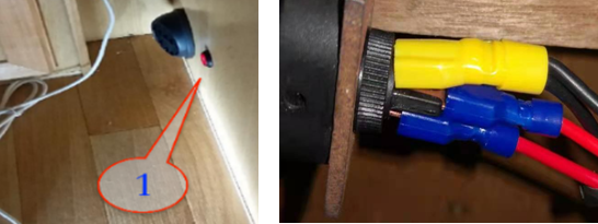
Installation suggestion:
Install a simple rocker switch (1) between the Heater and main battery power cable to allow you to shut down the unit completely when the heater is not being used for a long period. This is due to the Heater & Control Panel display continue to consume a very small amount of power when turned off.
8.6 Air flow around the Heater
8.6.1 Inflow

- a) Installation suggestion: Ensure fresh air can freely enter the area where you have mounted the Heater. This ensures the ambient air of the area to be heated can freely enter the air take of the Heater and the heat exchange chamber, to be discharged into the area to be heated.
- b) Vent can be painted to match wall colour for for artistic reasons. Also grill Vent with Insect Screen can be purchased at Bunnings for venting via wall to avoid any clashing.
9.LENGTH OF PIPES (for best performance)
9.1 Exhaust Pipe
- 9.1.1 The exhaust pipe length should be no longer than 0.8m. Any longer will void the warranty.
- 9.1.2 Any bend or angle in the exhaust pipe should be less than 90 degrees.
- a) An exhaust pipe any longer than that provided in the purchased package will promote carbo deposition in the first 0.6m of the exhaust pipe & the heaters performance will be reduced and ultimate failure will occur, and the warranty will be void and no claims recognised.
- b) Installation of the exhaust pipe must include a slight fall to the weep hole in the muffler for the discharge of condensation.
- c) The muffler must be installed with the weep hole pointing to the ground.
9.2 Ambient air intake into the heater.
- 9.2.1 The length of the ambient air intake duct into the Heater should be less than 1m, otherwise the Heater will overheat quickly & stop working due to high air flow resistance within the air intake duct.
- 9.2.2 Any bends within the length of the 1.0m air intake duct must be avoided or kept to a minimum. Any unavoidable bends should be less than 90 degrees.
- 9.2.3 Please note: A delivery fan of any appliance will have a significantly reduced performance if it is required to draw the required volume of air through a high resistance (long & curved) delivery duct.
9.3 Heated air delivery from the Heater into the heated air space
- 9.3.1 The length of the heated air delivery duct from the Heater should be less than 1m.
- 9.3.2 Any bends within the length of the 1.0m air intake duct must be avoided or kept to a minimum. Any unavoidable bends should be less than 90 degrees.
- 9.3.3 Please note: A delivery fan of any appliance will have a significantly reduced performance if it is required to draw the required volume of air through a high resistance (long & curved) delivery duct.
10. SHUTTING DOWN THE HEATER (Cooling)
- 10.1 Shut off the Heater using either the Control Panel or the Remote-Control unit which allows the computer to initiate the “Shut Down” sequence thus allowing the heater to Cool Down prior to shutting off.
- 10.2 Do not shut down the Heater without initiating the computerized cooling process as the high temperature within the aluminum body will cause damage to the unit and its components parts.
FAULT CODE DESCRIPTION
|
MACHINE MALFUCTION |
ERROR CODE | CORRECTIVE ACTION |
|---|---|---|
| undervoltage | E-01 | Raise the supply voltage |
| overvoltage | E-02 | Reduce the supply voltage |
| Ignition plug failure | E-03 | Check if the ignition plug is open or shorted |
| Oil pump failure | E-04 | Check if the oil pump is disconnected |
| Machine overheating | E-05 | Check the temperature sensor on the housing or if the fan speed is abnormal |
| Motor failure | E-06 | Check magnet polarity, Heated area target temperature sensor position, or loose terminals |
| Wire breakage failure | E-07 | Check the panel connection plug, the blue harness connection is loose or broken |
| Flame extinguished | E-08 | Check the oil circuit for air or wax blocking, resulting in poor oil supply |
| Sensor failure | E-09 | Check if the sensor plug is loose, or disconnected, shorted |
| Ignition failure | E-10 | Check if the oil circuit is blocked, or the oil is not smooth, the oil pump is stuck, the volatile oil is blocked due to oil problems, etc. The ignition does not burn properly |
When LCD display “E-03”, please consult our technician for assistance and fixing advice. Removing ignition plug by yourself will void the warranty.

There are two sensors on fan (in yellow circle) and one on control board (in red circle). When fan is spinning, they sense each other every semi-circle. They have to be placed with a certain distance for heater to work. If fan stop running when aluminum body is still working, it can cause overheating issue. If fan is too close to control board, it may damage the control board. Heater will not be working if distance is out of range.

Bending exhaust pipe over 90 degree is not recommended and will void the warranty. A hole has to be drill at the bottom of that part for the discharge of condensation.

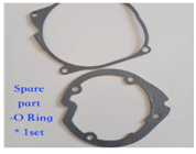
Gasket should be placed as flat as possible for the best seal performance.
Hot air duct pipe can be supported and protected by metal cover or pvc pipe.

Please consult our technician for assistance and advice, replacing burner by yourself will void warranty unless the carbon was caused by a defective heater or component.
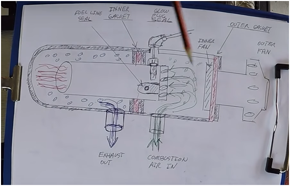
Insufficient fuel combustion: When the pump fuel volume is greater than the demand for a long time, the fuel combustion in the combustion chamber is not fully burned and it is easy to form carbon deposits. At this time, the heater can be dry burned for 3 to 5 times without pumping fuel, if the situation is not available Relieve and clean up carbon deposits.
Airflow is restricted: the total length of the intake pipe + exhaust pipe is too long. It is generally recommended that the total length of the two combined is less than 5 meters. If a muffler is installed, the total length should be shorter.
Low oil quality: Many drivers use oil from small gas stations. These oils are low-refined and blended oils in professional terms, mixed with a lot of bio-diesel smelted from waste oil. These low-quality oils contain more impurities. The moisture is large, there are more particulates and other substances after combustion, and long-term accumulation will cause carbon deposits in the combustion chamber.
Disassemble the parking heater, first use a flat-blade screwdriver to clean the carbon deposits on the burner, the combustion tube and the inner wall of the furnace, then clean the burner with a cleaning agent, and finally blow the burner with an air gun. If it is not ventilated, replace the burner ; Be careful not to damage any parts in the process of dismantling the parking heater and cleaning up the carbon deposits to avoid damage to the machine.
https://forums.ybw.com/index.php?threads/webasto-heater-frequent-burner-replacement.335013/
https://www.lubricationspecialist.com/blog/airtronic-carbon-buildup

